Why SU-8 Spin Coating Repeatability Often Degrades in Shared Research Cleanrooms
In many advanced research labs, SU-8 failures do not begin as catastrophic process breakdowns, they begin quietly. A wafer that coated perfectly last month suddenly develops severe edge bead accumulation. A microfluidic structure that previously showed clean vertical sidewalls starts exhibiting profile distortion. One researcher repeatedly achieves stable 100 µm coatings, while another using the same recipe struggles with trapped solvent defects and nonuniform thickness.
Eventually the discussion turns toward chemistry:
- “The SU-8 may have degraded.”
- “Perhaps the solvent absorbed moisture.”
- “Maybe this resist batch behaves differently.”
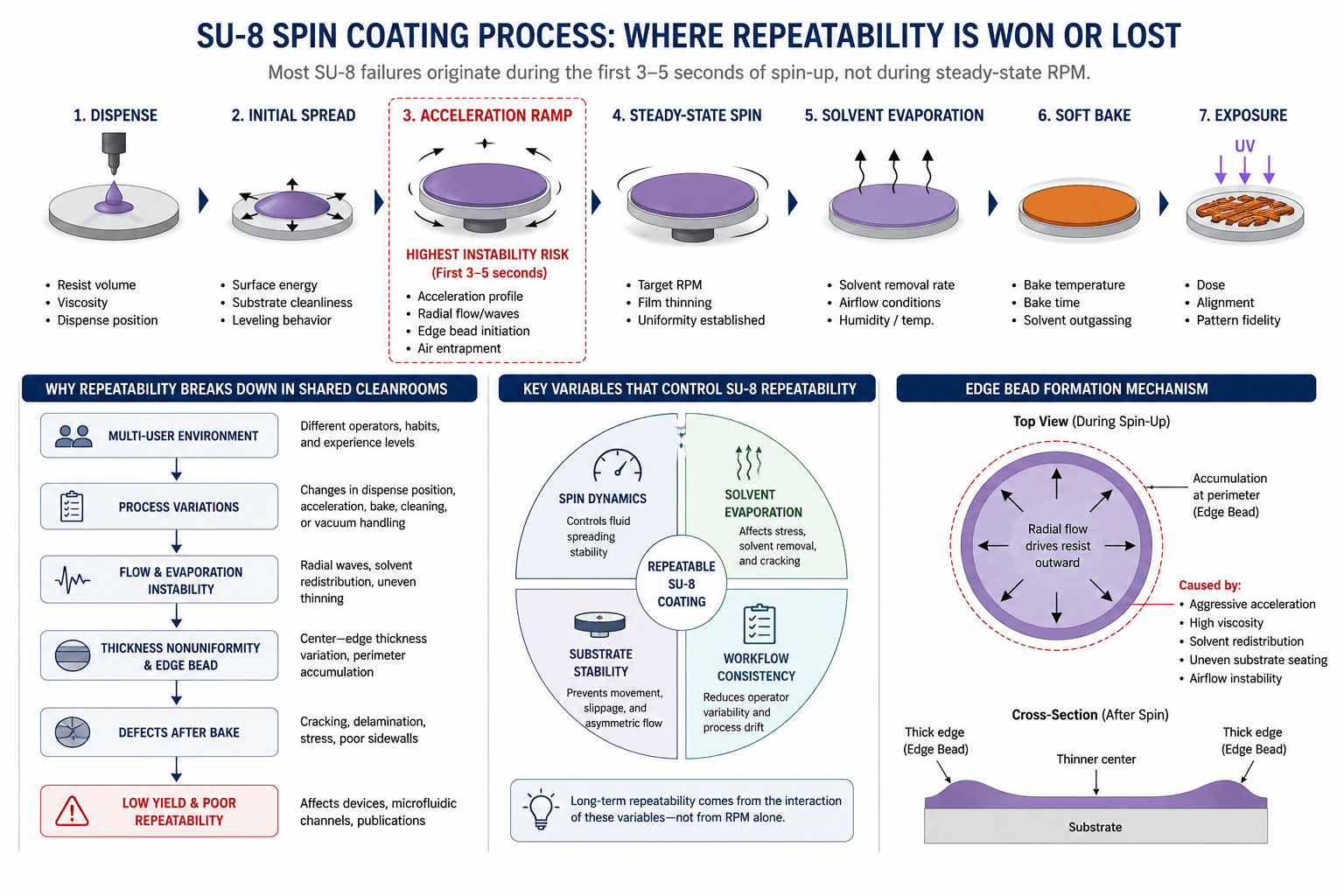
Sometimes that is true, but inside many MEMS and photolithography workflows, the underlying problem is often somewhere else entirely. In many shared cleanroom environments, SU-8 repeatability failures are frequently associated with process instability during acceleration, substrate holding, solvent evaporation, and multi-user operational variability.
In many university cleanrooms, researchers spend weeks modifying bake temperatures and resist recipes when the real failure source is mechanical instability during the first 3–5 seconds of spin-up.
Across German semiconductor and Mikrofabrikation research ecosystems in Dresden, Aachen, Karlsruhe, Freiburg, Munich, and Hamburg, researchers are no longer evaluating spin coaters based only on maximum RPM. They are evaluating whether a system can maintain stable thin-film behavior across months of shared laboratory operation. For SU-8 specifically, that is a far more difficult engineering problem than most specification sheets suggest.
What Is SU-8 Spin Coating?
SU-8 spin coating is a photolithography process used to deposit thick epoxy-based negative photoresist films onto wafers or substrates for MEMS fabrication, microfluidics, BioMEMS, optical waveguides, and semiconductor prototyping. The process requires tightly controlled acceleration, spin speed, solvent evaporation, and bake conditions to achieve uniform high-aspect-ratio structures. Unlike standard thin photoresist coating, SU-8 processing places significantly higher demands on:
- acceleration stability,
- substrate holding,
- vacuum consistency,
- solvent management,
- and workflow repeatability.
Why German Labs Care About SU-8 Repeatability
Shared semiconductor and microsystems cleanrooms increasingly operate under strong reproducibility requirements through initiatives linked to the European Chips Act, Silicon Saxony, Fraunhofer Institutes, Forschungsfabrik Mikroelektronik Deutschland (FMD), RWTH Aachen, IMTEK Freiburg, and Karlsruhe Institute of Technology. Many of these environments now operate highly shared multi-user fabrication infrastructures where:
- multiple PhD researchers use the same equipment,
- process recipes evolve continuously,
- substrates vary between projects,
- and publication timelines depend heavily on reproducibility.
In these environments, failed SU-8 runs are not simply material losses, they affect:
- cleanroom scheduling,
- doctoral research timelines,
- wafer utilization,
- device yield,
- and publication throughput.
That is why many German MEMS and microfluidics groups increasingly prioritize repeatability and long-term workflow stability over isolated RPM specifications.
Why SU-8 Behaves Differently From Standard Photoresists
SU-8 is fundamentally different from conventional low-viscosity photoresists because it was engineered for:
- thick-film lithography,
- high-aspect-ratio microstructures,
- permanent epoxy structures,
- and mechanically stable MEMS fabrication.
That creates process behavior that amplifies instability much more aggressively than standard thin-film coating.
Why SU-8 Processing Is Sensitive to Process Instability
| Process Variable | Operational Impact |
|---|---|
| High viscosity | Amplifies acceleration instability |
| Thick film deposition | Increases edge bead formation |
| Long bake cycles | Raises trapped solvent risk |
| High aspect ratio structures | Magnifies thickness variation |
| Slow solvent evaporation | Increases internal stress formation |
“Studies on evaporating capillary bridges and confined liquid systems have demonstrated how evaporation-driven flow can influence deposition morphology and material redistribution during drying processes.” — Ojha M., Kumar L., Bhardwaj R.1
This is one reason why SU-8 failures are common in:
- MEMS fabrication,
- BioMEMS,
- microfluidics,
- wafer-level packaging,
- optical waveguides,
- and multilayer lithography.
Why SU-8 Failures Often Originate From Process Variability Rather Than Chemistry Alone
One of the most misunderstood realities in thin-film fabrication is that researchers often assume defects originate primarily from:
- expired chemistry,
- viscosity inconsistency,
- substrate incompatibility,
- or resist degradation.
Yet in real cleanroom environments, many failures originate from operational variability instead.
Common Hidden Causes of SU-8 Repeatability Failure
- unstable acceleration ramps,
- substrate micro-slippage,
- inconsistent vacuum holding,
- uneven dispensing position,
- dehydration bake inconsistency,
- airflow disruption,
- substrate surface contamination,
- solvent residue contamination,
- vibration transfer,
- operator-dependent workflow drift.
These variables can influence coating repeatability, solvent evaporation conditions, and thin-film uniformity in shared processing environments.
Studies investigating airflow and substrate wettability effects during droplet evaporation demonstrate how local airflow conditions can alter evaporation dynamics and liquid redistribution behavior on solid substrates. — Mahato L.K., Bhardwaj R. 2
These variables directly influence:
- film thickness consistency,
- edge bead formation,
- sidewall geometry,
- adhesion reliability,
- and lithographic repeatability.
The 4 Variables That Actually Control SU-8 Repeatability
| Variable | Why It Matters |
|---|---|
| Spin dynamics | Controls fluid spreading stability |
| Solvent evaporation | Affects stress and cracking |
| Substrate stability | Prevents asymmetric coating |
| Workflow consistency | Reduces multi-user process drift |
Most long-term SU-8 repeatability problems emerge from interactions between these variables — not from a single isolated failure source.
Environmental Stability in SU-8 Processing
SU-8 processing can also be sensitive to environmental variation, particularly during thick-film coating and soft bake stages. In shared cleanrooms, fluctuations in:
- ambient humidity,
- temperature stability,
- airflow turbulence,
- and solvent vapor concentration
may influence solvent evaporation dynamics, adhesion behavior, internal stress formation, and coating repeatability.
Why RPM Alone Is a Misleading Metric in SU-8 Spin Coating
One of the most persistent misconceptions in spin coating is that higher RPM automatically produces better uniformity. In reality, SU-8 film formation depends on:
- angular velocity,
- acceleration profile,
- viscosity,
- substrate stability,
- solvent evaporation dynamics,
- and airflow behavior.
In simplified spin-coating models, film thickness is commonly approximated as dependent on resist viscosity and inversely related to angular velocity:
Where ω = angular velocity, h = film thickness, η = resist viscosity
This helps explain why instability during spin-up may contribute to measurable thickness variation in high-viscosity SU-8 coating.
Actual SU-8 film thickness and uniformity depend strongly on solvent evaporation kinetics, resist formulation, substrate surface energy, ambient humidity, dispense volume, and bake conditions. Empirical process calibration remains necessary for research-grade fabrication.
Why Acceleration Profiles Matter More Than Peak RPM
Many coating defects emerge during early acceleration stages — not during steady-state rotation. Aggressive acceleration ramps can contribute to:
- radial wave formation,
- edge thickening,
- solvent redistribution,
- trapped air pockets,
- and asymmetric spreading,
particularly in high-viscosity thick-film processes.
This becomes especially problematic during:
- thick SU-8 coating,
- large substrate processing,
- multilayer lithography,
- and high-aspect-ratio MEMS fabrication.
SU-8 Thickness vs Spin Speed Reference
| SU-8 Series | Approx Film Thickness | Typical RPM Range |
|---|---|---|
| SU-8 2005 | 5–10 µm | 3000–5000 RPM |
| SU-8 2050 | 50–80 µm | 1500–3000 RPM |
| SU-8 2100 | 100–200 µm | 500–1500 RPM |
Actual film thickness depends on viscosity, substrate energy, solvent evaporation dynamics, ramp dynamics, and process conditions. Thickness values are approximate reference ranges and vary with resist formulation, dispense conditions, solvent content, substrate geometry, and process calibration.
Example: Why a 100 µm SU-8 Film Suddenly Becomes Nonuniform
A common scenario inside shared university cleanrooms involves a process recipe that initially performs well under a single experienced researcher.
Months later, repeatability begins collapsing:
- edge bead formation increases,
- film thickness varies between wafers,
- and trapped solvent defects appear unpredictably.
In many cases, the chemistry itself has not changed.
The actual cause may be:
- a modified acceleration slope,
- slightly different dispense positioning,
- vacuum instability,
- or solvent residue buildup inside the chamber.
This is why advanced fabrication labs increasingly evaluate spin coating systems based on long-term operational consistency rather than isolated demonstration performance.
What Causes Edge Bead Formation in SU-8 Processing?
Edge bead formation remains one of the most persistent problems in thick photoresist coating.
| Failure Mechanism | Likely Root Cause |
|---|---|
| Thick perimeter accumulation | Aggressive acceleration |
| Asymmetric edge bead | Uneven substrate seating |
| Localized resist buildup | Airflow instability |
| Bead cracking after bake | Trapped solvent |
| Repeatability drift | Vacuum inconsistency |
Even small edge bead instability can interfere with wafer bonding, fine-alignment lithography, MEMS fabrication, and microfluidic channel accuracy.
Basic Spin Coater vs Research-Grade SU-8 Platform
| Feature | Basic Spin Coater | Research-Grade Platform |
|---|---|---|
| RPM stability | Moderate | High precision |
| Ramp control | Limited | Multi-step programmable |
| Vacuum stability | Variable | Controlled |
| Solvent resistance | Standard | Chemical-resistant |
| Repeatability | Operator dependent | Process controlled |
Challenges of Maintaining SU-8 Repeatability in Shared Cleanrooms
In many German Reinraum environments, equipment is shared across:
- MEMS groups,
- microfluidics teams,
- photonics researchers,
- thin-film electronics labs,
- and doctoral fabrication projects.
Over time this creates process drift when a coating workflow that initially performs well under one operator often becomes unstable once:
- recipes evolve,
- substrates change,
- cleaning practices vary,
- and workflow shortcuts accumulate.
Similar operational challenges are commonly encountered in shared academic and industrial cleanroom environments.
What Researchers Should Evaluate in a Spin Coater for SU-8
| Parameter | Why It Matters |
|---|---|
| RPM stability | Controls thickness consistency |
| Programmable acceleration | Reduces flow shock |
| Chuck stability | Prevents substrate movement |
| Vacuum consistency | Critical for thick films |
| Chemical resistance | Reduces solvent degradation |
| Recipe programmability | Improves operator consistency |
| Cleaning accessibility | Minimizes contamination drift |
Modern SU-8 workflows increasingly benefit from systems supporting:
- vacuum-assisted and vacuum-less substrate handling,
- interchangeable chucks,
- flexible substrates,
- multi-step acceleration profiles,
- and long-duration process stability.
Frequently Asked Questions About SU-8 Spin Coating
SU-8 coating may operate between several hundred and several thousand RPM depending on resist viscosity, target film thickness, substrate diameter, and process architecture. Thick-film lithography generally uses lower spin speeds combined with controlled acceleration profiles.
Nonuniform SU-8 films are commonly caused by unstable acceleration profiles, airflow disruption, uneven dispensing, substrate movement, vacuum instability, or chamber contamination.
SU-8 cracking often results from trapped solvent, excessive internal stress, rapid thermal transitions, or nonuniform solvent evaporation during coating and soft bake stages.
Edge bead formation is commonly linked to aggressive acceleration, thick resist viscosity, uneven substrate seating, or solvent redistribution during spin-up.
Yes. However, flexible substrate coating often requires vacuum-less handling strategies or specialized chuck configurations to maintain stable film spreading.
Multi-user cleanroom environments introduce variation in dispensing behavior, chamber cleaning, substrate preparation, acceleration settings, and workflow discipline. Over time this creates process drift.
For thick SU-8 processing, the most critical features are acceleration control, vacuum stability, substrate holding consistency, programmable recipes, and chemical-resistant chamber design.
Discuss Your SU-8 Process Requirements
If your workflow involves:
- MEMS fabrication,
- SU-8 lithography,
- microfluidics,
- thick photoresist coating,
- or high-uniformity thin-film deposition,
Researchers evaluating thick-film SU-8 spin-coating workflows often consider acceleration control, substrate handling stability, solvent management, and long-term operational consistency in addition to maximum RPM capability.
Discuss your substrate size, target thickness, SU-8 viscosity, and cleanroom workflow requirements with our engineering team to identify a stable coating configuration for long-term research process consistency.