
Spin Coater for Photolithography and Photoresist Coating: What Actually Matters
Photolithography is a nine-step chain where spin coating is the step where most first-time failures happen — not because the physics is difficult, but because the variables that break uniformity are subtle, and the wrong machine makes them invisible until you’ve wasted three batches of resist.
A spin coater for photoresist is used to produce controlled, uniform photoresist films on wafers and substrates. Achieving repeatable results depends on more than maximum RPM: RPM accuracy, acceleration and deceleration profiles, chuck selection, dispense conditions, and process control all affect final film thickness and uniformity.
The trade-off most researchers accept without naming it: buy a premium imported coater with a long service record, or buy a lower-cost unit and hope the precision holds. You shouldn’t have to choose; a well-engineered spin coater gives you both.
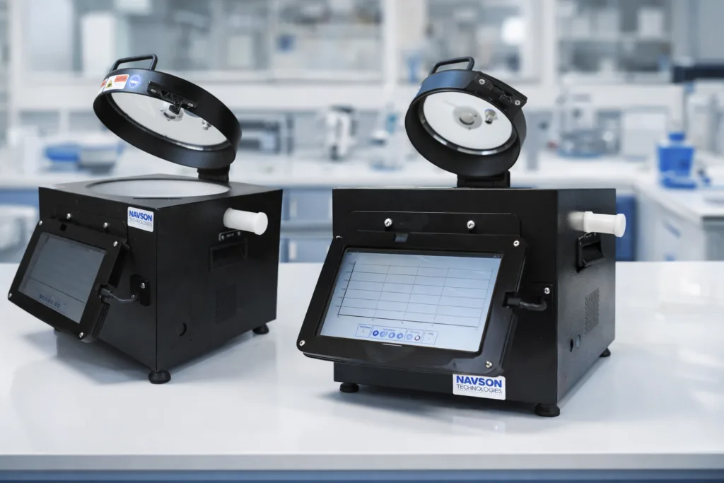
The Navson NT12000 is a precision spin coater designed for controlled, repeatable coating processes across research applications including polymers, photoresists, thin films and solution-processed materials. This article explains what the process demands of the machine — parameter by parameter — and where the NT12000 fits.
If your film thickness varies by more than 5% across a wafer, or you can’t reproduce Tuesday’s result on Wednesday, the sections below are where to look.
Key Takeaways
- Film thickness scales as the inverse square root of spin speed (t ∝ ω⁻¹ᐟ²). A 10% RPM error produces ~5% thickness error.
- Consistent spin-speed control helps improve film-thickness repeatability. Film thickness also depends on resist properties, dispense volume, acceleration, spin time and other process conditions.
- Acceleration profile matters as much as final RPM. Thick resists (SU-8, AZ 4620) need multi-step ramps to avoid striations.
- Chuck selection affects substrate holding and stability during spinning and should be based on the substrate’s size, shape and surface characteristics.
- Recipe repeatability is the #1 differentiator between a working lab and a struggling one. Lock the recipe; log every run.
- 6″ vs. 10″: choose based on your substrate size in 3 years, not today.
What Photoresist Spin Coating Actually Requires
Spin coating produces a uniform thin film by balancing centrifugal force, viscous flow, and solvent evaporation. The machine must deliver four things simultaneously: stable rotational speed, controlled acceleration, secure substrate holding, and a clean, chemically inert environment. Here’s what “uniform” means in practice:
| Resist type | Target thickness | Uniformity spec (3σ) |
|---|---|---|
| i-line / g-line (AZ 4620, S1818) | 1–3 µm | < 2% |
| KrF / ArF | 0.1–0.5 µm | < 0.5% |
| Thick-film negative (SU-8, AZ 4620) | 10–100 µm | Striation-free |
State-of-the-art research spin coaters achieve <0.5% thickness uniformity (3σ) on 200 mm wafers with proper environmental control and optimized dispense/spin recipes. For most academic and pilot-line work, <2% is the working target. This is also the frame for selecting a spin coater for photoresist in semiconductor research: the question isn’t “what’s the max RPM?” but “does this machine hold the parameters I need, repeatably, for my specific resist and substrate?”
What RPM Do I Need for Photoresist?
There is no single number, the answer depends on resist viscosity, solids content, and target thickness. Choosing a spin coater for photoresist therefore starts with the resist formulation and target film thickness, not simply the machine’s maximum RPM. The governing relationship (Erdman–Emslie, 1966; extended by Meyerhofer, 1979) is:
t ∝ ω⁻¹ᐟ²
Practical ranges:
| Resist type | Typical RPM | Spin duration | Example |
|---|---|---|---|
| i-line positive (S1818, AZ 4620) | 2,000–5,000 | 30–60 s | S1818: ~1.9 µm at 4,000 RPM |
| KrF / ArF | 4,000–8,000 | 20–40 s | Sub-micron films |
| Thick negative (SU-8, AZ 4620) | 500–2,000 | 30–120 s | Multi-step profile required |
| PMMA / PDMS (polymer) | 1,000–6,000 | 30–60 s | Viscosity-dependent |
The math that matters: A 1% change in spin speed produces approximately a 0.5% change in film thickness. At 3,000 RPM, ±1% speed accuracy (±30 RPM) gives you ±0.5% thickness variation. At ±1 rpm control (production-grade), thickness stability from speed alone is <0.02%.
For a 1.8 µm i-line target, ±5% speed error = ±90 nm — that’s enough to shift your exposure dose window and ruin a batch.
What this demands from the machine:
For a spin coater for photoresist, the machine should provide:
- Closed-loop BLDC motor with speed feedback (not open-loop, not brushed)
- ±1% accuracy at setpoint across the full range
- 50 RPM floor (for thick resists without splashing)
- 12,000 RPM ceiling (for sub-100 nm targets)
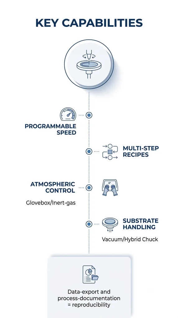
The NT12000 runs 50–12,000 RPM with ±1% accuracy on a sealed BLDC motor (IP65).
Why Acceleration and Ramp Profile Matter
Most researchers set a spin speed and a duration; what they don’t control is how fast the wafer gets to that speed. The acceleration profile determines initial film distribution, striation formation, and edge bead severity. This is particularly important when a spin coater for photoresist is being used for thick or multi-layer resist processes, where the acceleration profile can influence initial film distribution and final uniformity. So here are three practical effects:
- Initial distribution. A slow ramp (500 RPM/s) gives a thicker, more uniform initial layer before thinning begins. A fast ramp (5,000 RPM/s) throws off more liquid early, producing a thinner but less uniform film.
- Striations in thick resists. SU-8 at 10+ µm needs a two-step profile: slow spin at low RPM to spread, then ramp to thin. A single-step fast spin produces concentric rings. This is the single most common failure mode in MEMS labs.
- Edge bead. Rapid acceleration increases edge bead volume because the meniscus doesn’t have time to stabilise.
Typical thick-film profile (SU-8, 25 µm target):
Step 1: 0 → 500 RPM at 500 RPM/s, hold 30 s     (spread)
Step 2: 500 → 3000 RPM at 2000 RPM/s, hold 20 s  (thin)
Step 3: 3000 → 0 RPM at 1000 RPM/s               (decel)
For standard i-line photoresist, a single ramp at 2,000–5,000 RPM/s to 2,000–4,000 RPM for 30–60 s is sufficient. The NT12000 supports programmable acceleration from 1 to 8,000 RPM/s with 10-step recipes (customisable to 100 steps). For most photoresist work, you’ll use 1–3 steps. For thick-film or high-aspect-ratio work, the multi-step capability is where the machine earns its keep.
Vacuum vs. Non-Vacuum Chuck: Which Do You Need?
A wafer that shifts 0.5 mm during spin produces a thickness gradient that no amount of RPM optimization can fix. For a spin coater for photoresist, the holding mechanism must grip securely without introducing contamination, damaging the substrate, or interfering with film uniformity.
| Chuck type | Best for | Limitation |
|---|---|---|
| Vacuum (650 mmHg) | Flat, unpatterned wafers; glass slides | Can cause delamination on patterned or fragile substrates; “stiction” on wet wafers |
| Vacuum-less (mechanical) | Patterned wafers, fragile substrates, glass with thin films | Slightly less grip force; not ideal for very small substrates |
| Hybrid / both available | Labs that handle both flat and patterned substrates | — |
Practical rule: If you’re coating on flat silicon or glass → vacuum is fine. If you’re coating on patterned wafers (post-etch, post-CMP) or on fragile thin films (perovskite, 2D materials) → vacuum-less avoids the “stiction” problem where a wet, patterned wafer bonds to the chuck face and cracks on release.
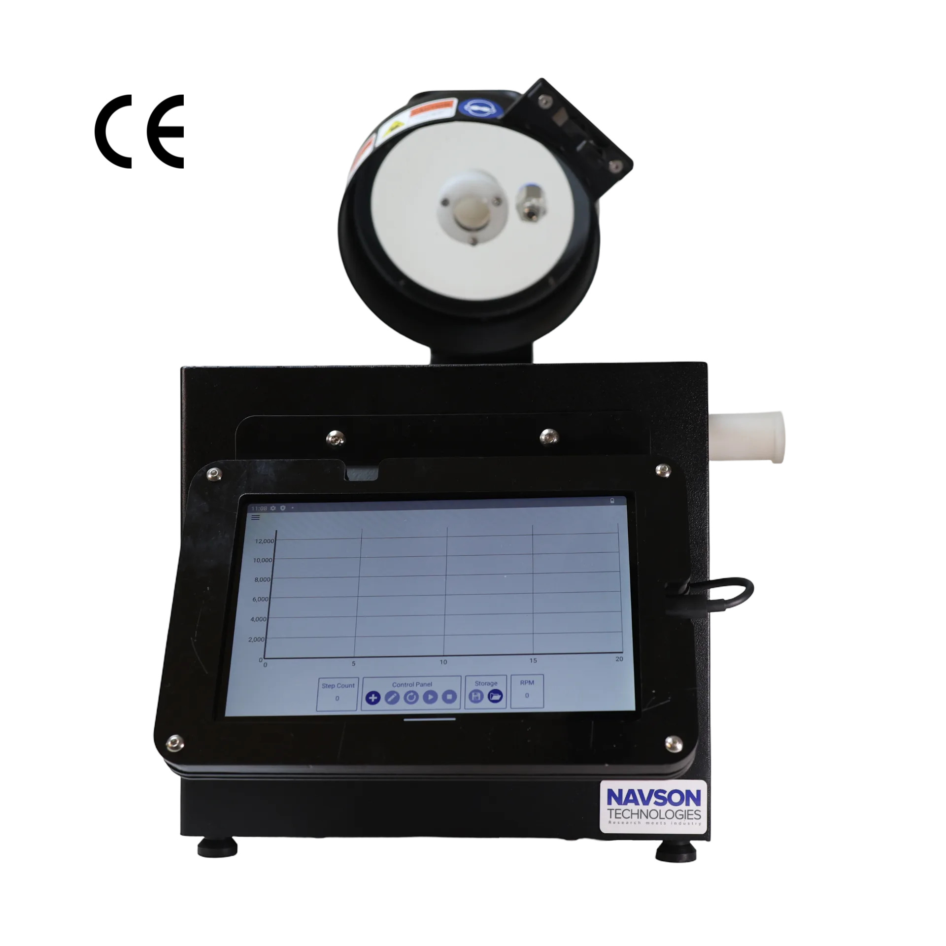
The NT12000 ships with both vacuum and vacuum-less chucks as standard on the 6″ model. Custom chuck geometries (5–100 mm on 6″; 5–200 mm on 10″) are available for non-standard substrates.
Film Thickness: What Controls It and How to Hit Target
When evaluating a spin coater for photoresist, these variables should be considered together because changing one process parameter can alter the final film thickness.
Dry film thickness is a function of seven variables:
| Variable | Direction | Practical note |
|---|---|---|
| Spin speed (ω) | Faster = thinner (t ∝ ω⁻¹ᐟ²) | Primary control |
| Spin duration | Longer = thinner (until solvent exhausted) | Diminishing returns past 60 s for most resists |
| Resist viscosity | Higher = thicker at same RPM | Check vendor spin curve |
| Solids content | More solids = thicker dry film | — |
| Dispense volume | More = thicker (up to a point) | Use calibrated pipette or auto-dispenser |
| Ambient humidity | Higher RH = thicker, less uniform | ~2 nm per 1% RH for some resists (e.g., AR-P 3510) |
| Substrate flatness | Warped wafer = local variation | Check with flatness gauge |
The fastest way to hit target: Pull the vendor’s spin curve (e.g., S1818: 2.6 µm at 2,000 RPM → 1.5 µm at 7,000 RPM). Pick the RPM that gives your target thickness. Coat three wafers. Measure with ellipsometry. Adjust ±200 RPM. Lock the recipe.
- If you need sub-100 nm films (EUV resist development): 8,000–12,000 RPM, tight accuracy, low ambient humidity.
- If you need 10–100 µm thick films (SU-8, AZ 4620): 500–2,000 RPM, slow ramp, long spin, multi-step profile.
- If you need multi-layer stacks: sequential recipes without re-loading.
Particulate Control: What “Cleanroom Compatible” Actually Means
“Cleanroom compatible” is used loosely, so here’s what the machine actually needs to do at each environment level:
| Environment | Particulate budget | Machine requirement |
|---|---|---|
| Open bench (most university labs) | Uncontrolled / ~ISO 7–8 ambient | Enclosed chamber; easy to clean between runs |
| Laminar flow hood (pilot lines, SCL, SAC) | ~100 particles/m³ (ISO 6) | No corroding metal; smooth geometry |
| ISO 5 cleanroom (production, imec, ARCNL) | ~3 particles/m³ | Machine must not be a particle source |
The two biggest particle sources in spin coating are metal corrosion (stainless steel bowls corrode with resist solvents and shed particles) and mechanical wear (seals, O-rings, machined surfaces).
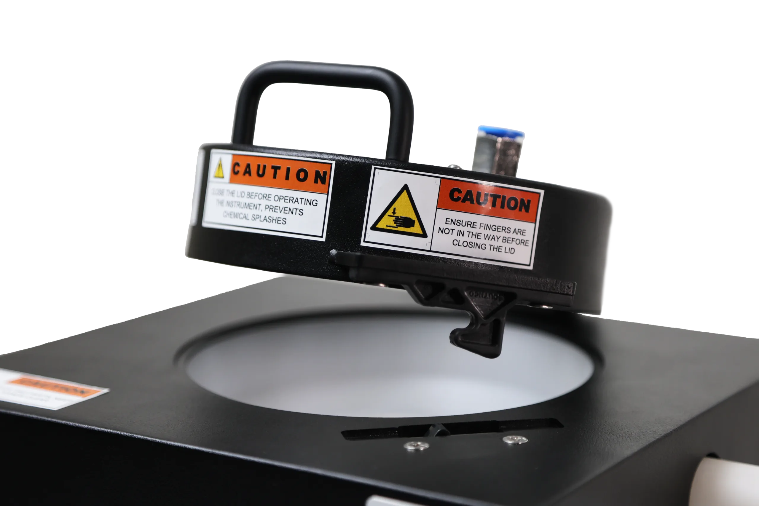
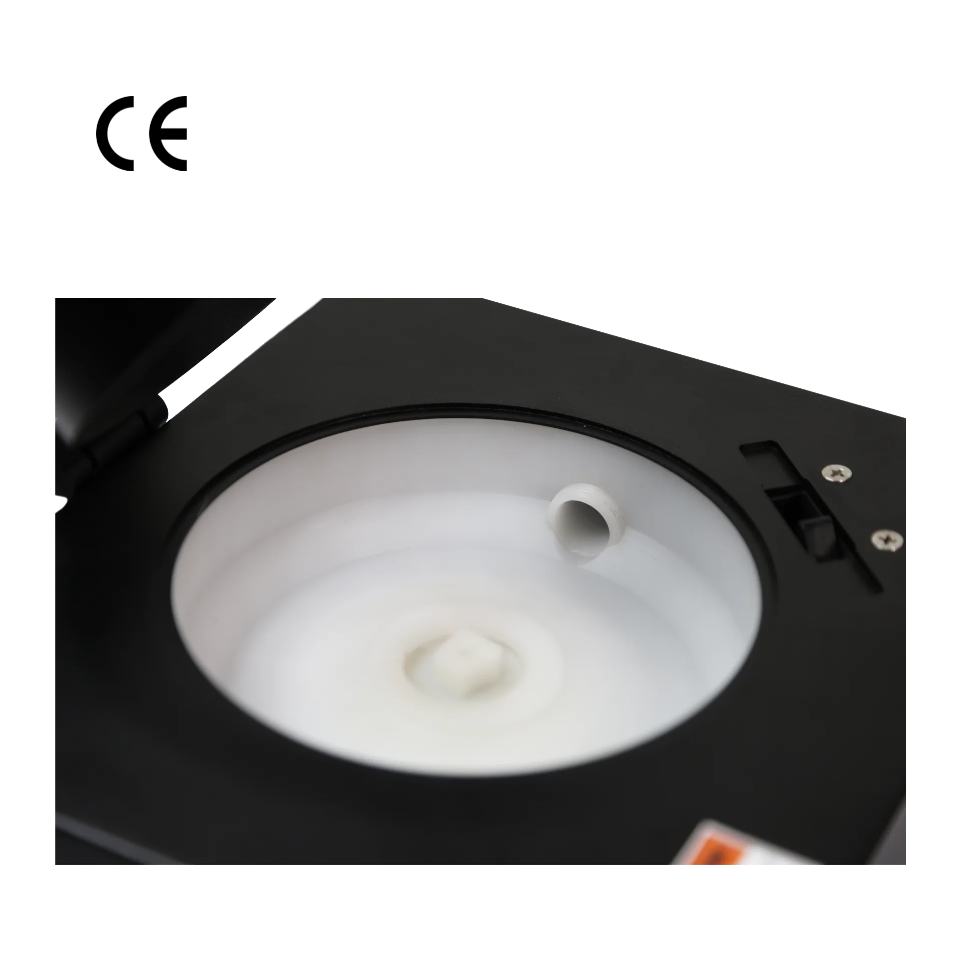
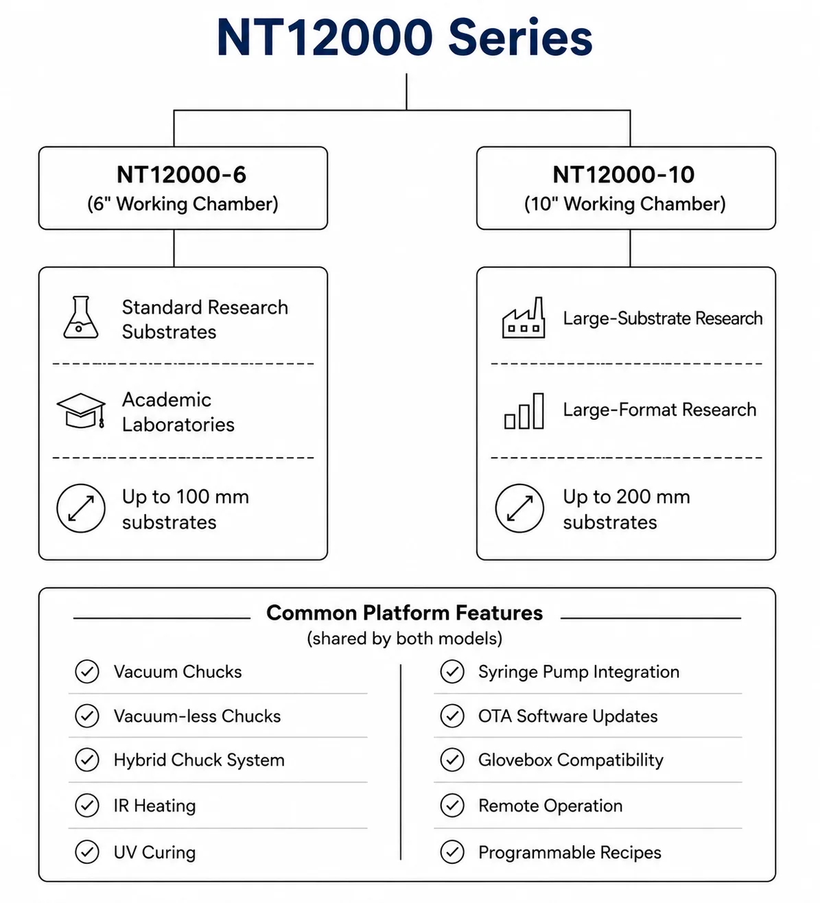
The NT12000’s 100% natural polypropylene working chamber eliminates both. No metal contact. No lubricants. No rubber seals that off-gas. The transparent acrylic lid (UV-safe) lets you observe the spin without opening the chamber — critical in a controlled environment where every lid open/close is a particle event.
For Indian labs without a full cleanroom: An enclosed PP chamber with a UV-safe lid and side drainage gives you a meaningful particle reduction over an open-bowl coater. It’s the single highest-ROI upgrade for film quality.
Chemical Compatibility: Will the Chamber Survive Your Solvents?
Photoresist processing involves aggressive chemistries, and the chamber material must resist all of them without leaching additives into your film:
| Chemical | Use | PP chamber |
|---|---|---|
| PGMEA / PGME | Resist solvent | Resistant |
| Acetone | Rinse / strip | Resistant |
| IPA | Rinse | Resistant |
| TMAH 2.38% | Developer | Resistant |
| HCl, H₂SO₄, HNO₃ (≤ 1 M) | RCA wet clean | Resistant |
| NaOH / KOH (≤ 1 M) | Wet clean | Resistant |
| NMP | SU-8 developer | Resistant |
| Toluene | Rinse | Resistant |
Limitation: The PP chamber is not rated for concentrated (>90%) H₂SO₄ or hot concentrated halogenated solvents.
Practical benefit: You can soak the bowl in acetone overnight to remove dried SU-8 without worrying about material degradation. A stainless-steel bowl will pit. A polycarbonate bowl will cloud.
How to Get Repeatable Spin Coating (and What to Do When It Breaks)
This is the unglamorous question that separates a working lab from a struggling one. “I got a good film on Tuesday. Why is Wednesday’s film 8% thicker?”
If your equipment is the weakest link in the experiment, every downstream step — exposure, development, etch — inherits the error. Repeatability is fundamental when using a spin coater for photoresist because it makes the coating process and resulting data defensible in a thesis defense, peer review, or procurement audit. Here’s how repeatability breaks down at four levels:
- Machine-to-machine — different motor calibration, chuck flatness, chamber geometry
- Run-to-run — varying dispense volume, ambient T/RH, resist viscosity drift
- Operator-to-operator — different dispense technique, manual timing
- Day-to-day — resist lot change, chuck wear, ambient shift
What the machine controls: RPM (±1%), acceleration profile, spin duration, step parameters.
What it can’t control (but you can monitor): dispense volume (use auto-dispenser), ambient conditions (log them), resist age/lot (track in lab notebook).
The 10-step (100-step) recipe system with unlimited storage in non-volatile memory means you lock in a known-good recipe and every operator runs the same parameters. This is the single most important feature for a multi-student lab in India or a multi-PostDoc group in Europe.

Troubleshooting: Your Film Is Non-Uniform
| Symptom | Likely cause | First check |
|---|---|---|
| Thickness gradient (thick one edge) | Wafer shifted; chuck not centred | Re-seat wafer; check chuck flatness |
| Concentric rings / striations | Too-fast ramp on thick resist | Reduce ramp rate; add low-RPM spread step |
| Edge bead too large | Rapid acceleration; excess dispense | Slow the ramp; reduce dispense 10–20% |
| Random variation (±5%+) | Particulate; inconsistent evaporation | Clean chamber; log ambient RH |
| Film delaminates after bake | Adhesion failure (priming), not spin | Check HMDS step; verify substrate cleaning |
| Run-to-run drift (>3%) | Dispense volume; resist viscosity | Use auto-dispenser; check resist lot/age |
Why Data Logging Matters (More Than You Think)
A spin coater that doesn’t log its runs makes troubleshooting guesswork and your publication methods section weaker than it should be. So here are FOUR reasons to insist on it:
- Publication. Your methods section states “coated at 3,000 RPM for 30 s, ramp 2,000 RPM/s, on a Navson NT12000 (±1% speed accuracy).” If a reviewer asks for the actual RPM trace, you produce it.
- Troubleshooting. “The film was non-uniform on run #47.” With a log, you correlate the thickness map to the RPM trace and identify whether it was a speed dip, a ramp anomaly, or an operator error.
- Traceability. EU research funding (Horizon Europe, ERC) increasingly requires process parameter traceability. A USB-exportable log is the minimum.
- Lab management. When a thesis examiner, peer reviewer, or procurement audit asks for your process parameters, you produce them — not reconstruct them from a lab notebook.
The NT12000 logs full run data (RPM vs. time, step parameters, duration) and exports via USB. The 7″ touch display shows a live RPM vs. time graph during the spin.
Tip: Export the log after every run. Archive it with your wafer map and thickness measurement. Over 6 months, you’ll build a dataset that tells you your process capability (Cpk) and when to recalibrate.
6″ vs 10″ Spin Coater: Which Do You Need?
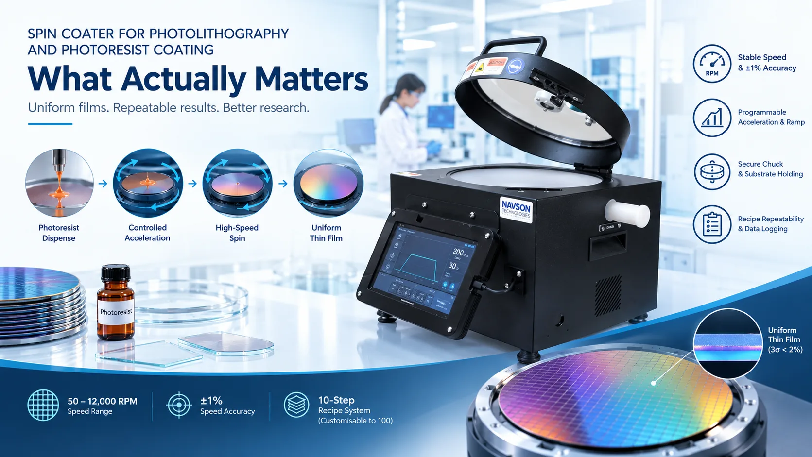
The answer is almost always: “What will your substrates look like in 3 years?”
| Factor | NT12000 (6″) | NT12000 (10″) |
|---|---|---|
| Max substrate | 100 mm (4″) | 200 mm (8″) |
| Chamber | 150 mm dia. × 75 mm | 250 mm dia. × 75 mm |
| Footprint | 260 × 260 × 320 mm | 334 × 334 × 320 mm |
| Weight | 12 kg | 14 kg |
| Standard chucks | Vacuum (to 50 mm), Universal (to 100 mm), Vacuum-less (25×25 to 100 mm) | Vacuum (to 50 mm), Universal (to 100 mm), Custom (5–200 mm) |
| Glovebox | Designed for it | Optional |
| Best for | Perovskite, OLED, nanomaterials, small-batch MEMS | 100–200 mm wafer photoresist lithography, large-area thin films |
Rule of thumb:
- Glass slides, 50–75 mm wafers, small MEMS → 6″
- 100 mm silicon wafer photoresist lithography → 10″ (a 100 mm wafer in a 6″ chamber leaves too little margin for edge effects)
- 150 mm wafer work → 10″
- Glovebox (perovskite, 2D materials) → 6″ (compact footprint)
If this is a new grant, a replacement for an ageing unit, or a first purchase for a newly funded lab: prioritise the substrate size your funded project requires, not the one your current experiments use.
For EU labs doing 300 mm process development: the NT12000 is a research-scale complement to production coaters, not a replacement. Use it for R&D, new resist trials, and small-batch characterization.
NT12000: Full Specification at a Glance
| Parameter | Specification |
|---|---|
| Speed range | 50–12,000 RPM |
| Speed accuracy | ±1% |
| Acceleration | 1–8,000 RPM/s (programmable) |
| Steps per recipe | 10 (customisable to 100) |
| Recipe storage | Unlimited, non-volatile |
| Max program time | 10,000 s |
| Motor | BLDC, IP65 sealed |
| Chamber | 100% natural polypropylene, zero metal |
| Lid | Translucent brown acrylic, UV-safe |
| Vacuum | 650 mmHg max |
| Chuck options | Vacuum, vacuum-less, hybrid; 5–100 mm (6″) / 5–200 mm (10″) |
| Display | 7″ touch, live RPM/time graph |
| Data logging | Full trace, USB export |
| Noise | < 55 dB at max speed |
| Inert atmosphere | N₂ purging port (pneumatic) |
| Drainage | Side pipe, PP; optional 300/500 mL spillage containers |
| Power | 220–240V AC, 50 Hz [VERIFY: confirm exact range from datasheet] |
| Weight | 12 kg (6″) / 14 kg (10″) |
Optional add-ons:
| Add-on | Why you’d want it |
|---|---|
| Auto-dispenser (250 µL micro-syringe) | Eliminates #1 source of run-to-run variation |
| IR heating (RT–200 °C) | Inline soft bake; wafer stays in chamber |
| UV lid (365 nm) | UV-curable resists; observation without opening |
| PC connectivity (Windows) | Remote recipes, batch logging, LIMS integration |
| Oil-free vacuum pump | No oil mist in cleanroom environment |
Before You Order: Practical Questions
These come up in every technical enquiry, and answering them here saves an email exchange.
- Lead time: [VERIFY: confirm current standard lead time. Custom chuck or add-on configurations may add X weeks.]
- Warranty and service: [VERIFY: confirm current terms — e.g., 12-month comprehensive, extendable.] Service support is available through Navson directly (India) and through regional distributors in Europe (including PI-KEM, UK).
- Documentation: Technical datasheet, operation manual, and CE documentation [VERIFY: confirm CE marking status for EU market] are provided with every unit.
- Quotation pathway: For a formal quote with configuration specifics, include your substrate size, resist type, target film thickness, and chuck requirement (vacuum or vacuum-less). Contact Navson Technologies directly or through your regional distributor.
Application data, institutional references, and published research using the NT12000 are available on request. [See Research Papers]
What This Article Doesn’t Cover
Photoresist selection (i-line vs. KrF vs. ArF vs. EUV), exposure alignment and dose optimisation, development chemistry, etch transfer, and metrology are separate conversations. The spin coat is where the film is born. A bad coat can’t be fixed by a good exposure.
The Navson NT12000 is manufactured in Chennai, India, and is available through direct sales and regional distributors in India and Europe. For application-specific configuration, recipe development support, or a technical demo —
Frequently Asked Questions
There is no single number. For i-line resists targeting 1–3 µm, 2,000–5,000 RPM for 30–60 s is typical (S1818 gives ~1.9 µm at 4,000 RPM). For KrF/ArF sub-micron films, 4,000–8,000 RPM. For thick-film negative resists (SU-8, AZ 4620), 500–2,000 RPM with a slow ramp and multi-step profile. The exact value depends on resist viscosity and solids content. Use the vendor’s spin curve as a starting point and calibrate with ellipsometry.
The core physics is identical. The practical differences: photoresist work typically demands tighter RPM accuracy (±1%), lower ambient particulate, and data logging for traceability. Polymer work (PMMA, PDMS, SU-8) often needs lower RPM ranges, longer spin times, and more aggressive chemical resistance (NMP for SU-8). A well-configured machine covers both.
Three things matter most: (1) RPM accuracy and stability (±1% at setpoint), (2) a controlled acceleration profile (not just a final speed), and (3) a clean, enclosed environment. If uniformity is still >2% after addressing these, check dispense volume consistency and ambient humidity. For production-grade <0.5% uniformity, you also need controlled dispense (dynamic or auto-dispenser) and stable ambient conditions.
The 6″ model handles substrates up to 100 mm; the 10″ model handles up to 200 mm. If you’re doing 100 mm wafer photoresist lithography, the 10″ model gives you the chamber clearance you need. If you’re working with glass slides or small MEMS chips, the 6″ model is sufficient and more compact (and glovebox-compatible).
From sub-100 nm (high-RPM spin of low-viscosity resist) to >100 µm (low-RPM, long-duration spin of high-viscosity resist like SU-8). The practical limit is set by resist properties (viscosity, solids content) and the machine’s RPM range and stability, not by the spin-coating process itself.
For a 100 mm wafer with standard i-line resist: 2–5 mL is typical. For 200 mm: 5–10 mL. For glass slides (25×75 mm): 0.5–1 mL. The exact volume depends on resist viscosity and target thickness. Use a calibrated pipette or the NT12000’s optional auto-dispenser (250 µL micro-syringe) for run-to-run consistency. Excess is flung off during spin; the key is consistency, not precision to the microlitre.